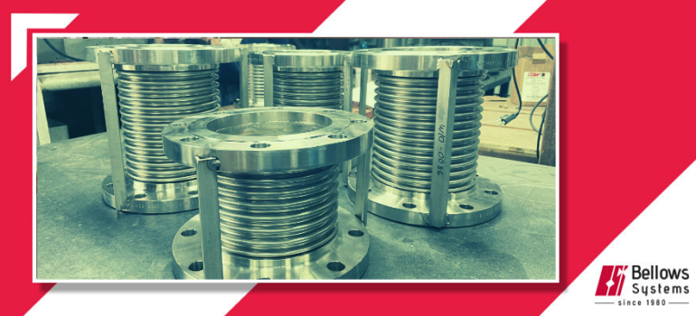
Bellows Systems has been making piping engineers lives easier by providing cost effective, engineered piping bellows and expansion joint solutions for their piping designs
Piping engineers are continuously faced with problems involving thermal movement, instability, limiting forces on equipment, and absorption of vibrations. The piping design must balance the economics of pipe loops and offsets, space, and fabrication against the cost of expansion joints.
Bellows Systems has made piping engineers’ lives easier by providing cost effective, engineered bellows and expansion joint solutions for their piping designs. Its Kopperman Division established in 1894 is one of the oldest manufacturers of expansion joints.
Piping bellows and expansion joints may be used in the following areas
- to absorb direct axial expansion or contraction,
- to absorb equipment vibration,
- to provide limitation of forces applied to critical equipment
- to improve line stability through reduction and control of loads on pipelines.
Size Ranges : We offer a complete lineup of piping expansion joint design options and standard sizes ranging from as small as 1” to 48” pipe OD.
Single and Multi ply : We can fabricate bellows from single ply wall thickness of 0.004” to 0.072” and multi-ply designs with up to 6 layers for different pressure classes and vibration loading.
Root Reinforced Bellows : Our high-pressure expansion joints can optionally be constructed with root reinforced bellows designs with integral root rings or equalizing rings.
Let's Talk About Your Project

Single
Expansion Joint
A bellows with end connections, designed to absorb all movements of the piping system in which it is installed. An expansion…

Universal
Expansion Joint
A universal expansion joint is an assembly containing one or two bellows connected by a center pipe and equipped with tie rods.

Hinged
Expansion Joint
A hinged expansion joint is an assembly designed to absorb angular rotation in the plane perpendicular to the hinge pins.

Gimbaled
Expansion Joint
A gimbal expansion joint is an assembly designed to absorb angular movement in any plane. The gimbal hardware consists…
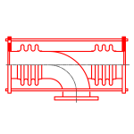
Pressure Balanced
Expansion Joint
A pressure balanced expansion joint is an assembly designed to absorb axial movement and /or lateral deflection...
Anchors, Guides and Supports
Other elements of a piping system that impact expansion joint design considerations.
PIPE ANCHORS

Pipe Anchors limit the length of each segment of the piping system, the thermal and mechanical changes in dimension in each segment and where Expansion Joints are used, they establish the limits of movement each expansion joint must absorb.
Pipe Anchors, designed to withstand all the forces and moments which will be imposed on them, are classified either as (1) Main or Full-Thrust Anchors or as (2) Intermediate Anchors. Regardless of whether Expansion Joints are used or not, anchors must be installed in every piping system. In certain applications it is desirable to have a sliding anchor, of either type, which will permit limited movement in one direction and absorb all forces and moments applied to it from any other direction.
In most applications, the major pieces of connected equipment such as turbines, pumps, compressors, heat exchangers, re actors, etc., function as anchors. Additional pipe anchors are usually located at valves, at changes in the direction of the pipe, at blind ends of pipe and at major branch connections. One or more expansion joints must, of course, be provided in each of the individual pipe sections to provide adequate flexibility. See Section 7 for typical expansion joint applications.
DO NOT INSTALL MORE THAN ONE EXPANSION JOINT BETWEEN THE SAME TWO ANCHORS IN ANY STRAIGHT PIPE SECTION UNLESS EACH JOINT IS EQUIPPED WITH LIMIT RODS.
Where expansion bends are used in the same line with an expansion joint, the section of pipe containing the bend must be isolated from the section containing the expansion joint by means of anchors.

Intermediate Pipe Anchors
An intermediate pipe anchor must be designed to withstand the forces and moments imposed upon it by each of the pipe sections to which it is attached.
In the case of a pipe section containing one or more expansion joints, these will consist of the forces and/ or moments required to deflect the expansion joint or joints, the full rated movement and the frictional forces due to pipe alignment guides, directional anchors and supports.
Note that an intermediate anchor does not have to be designed to withstand the pressure thrust, since this force is always absorbed by other anchors or by devices on the expansion joints such as limit rods, tie rods, swing bars, hinges, or gimbals.
In certain applications, however, it may be necessary to consider the weight of the pipe, fittings, insulation and flowing medium, as well as various other forces and moments resulting from wind loading, bending of one or more pipe sections, etc. The net loading on the anchor can be calculated by a summation of the moments about the anchor point and by the vector addition of all forces acting upon it.
Main Pipe Anchors

A main pipe anchor must be designed to withstand the forces and moments imposed upon it by each of the pipe sections to which it is attached. In the case of a pipe section containing one or more expansion joints, these will consist of the full line thrust due to pressure and flow, the forces and / or moments required to deflect the expansion joint or joints the full rated movement, and the frictional forces due to the pipe alignment guides, directional anchors, and supports.
In certain applications, it may be necessary to consider the weight of the pipe, fittings, insulation and flowing media, as well as various other forces and moments resulting from wind loading, bending of one or more pipe sections, etc. The net loading on the anchor can be calculated by C! summation of the moments about the anchor point and by the vector addition of all forces acting upon it.

PIPE GUIDES AND GUIDING
Correct alignment of the pipe is very important in the proper functioning of an expansion joint. Although expansion joints are designed and built for long and satisfactory life, maximum service will be obtained only when the pipeline has the recommended number of guides and is anchored in accordance with good engineering practice.
Pipe guides are necessary to ensure proper application of movement to the expansion joint and to prevent buckling of the line. Buckling may be caused by a combination of two things: (1) the flexibility of the expansion joint and (2) the compressive loading on the pipe resulting from pressure thrust in the expansion joint which causes the pipe to act like a slender column with end loading.

A pipe alignment guide is a form of sleeve or framework fastened to some rigid part of the installation which permits the pipeline to move freely in only one direction, along the axis of the pipe. Pipe alignment guides are designed primarily for use in applications involving axial movement only but may also be used in certain applications involving lateral deflection and angular movement.
A planar pipe guide is a pipe alignment guide modified to permit limited movement and/ or bending of the piping in one plane. It is used only in applications involving lateral deflection or angular rotation resulting from “L” or “Z” shaped piping configurations.
Proper design of both pipe alignment guides and planar pipe guides should allow sufficient clearance between the fixed and moving parts of the alignment guide to ensure proper guiding without introducing excessive frictional forces.
Planar pipe guides must, however, be designed with additional clearance in one direction to permit the intended lateral deflection and/or bending of the pipe to take place.
A U-Bolt, pipe hanger or roller support, which only supports the weight of the line, cannot take the place of either a proper pipe alignment guide or a planar pipe guide. Material from which pipe alignment guides and planar pipe guides are made must provide strength and rigidity under design operating conditions and be sufficiently resistant to corrosion and wear to prevent eventual malfunction of the guide. Although field bolting of pipe alignment and planar pipe guides to the rigid parts of the installation is preferable, field welding is acceptable, provided that inaccuracies or excessive weld shrinkage (do not destroy the effectiveness of these guides. Suitable pipe alignment and planar pipe guides may be obtained from reliable manufacturers of this type of equipment. It should be noted that the effectiveness of pipe alignment and planar pipe guides can be destroyed by improper installation. Consequently, care must be taken to ensure proper alignment of the guide itself. In applications involving axial movement only, the use of a single pipe alignment guide should be avoided where it may act as a fulcrum imposing lateral deflection or angular rotation on an expansion joint. However, in certain applications involving lateral deflection or angular rotation, a single pipe guide may be adequate.
In locating pipe alignment guides for applications involving axial movement only, it is recommended that the expansion joint be located close to an anchor and that the first pipe guide be located a maximum distance of four pipe diameters from the expansion joint. The distance between the first pipe guide and the second must be a maximum of fourteen pipe diameters.
PIPE SUPPORTS

A pipe support is any device which permits free movement of the piping and carries its dead weight and the weight of the contained fluid. Pipe supports cannot be substituted for pipe alignment guides or planar pipe guides.
However, these devices cannot control the direction of the pipeline movement as does a pipe alignment guide or planar pipe guide. The recommendations given previously for pipe anchors and guides represent the minimum requirements for controlling pipelines containing expansion joints and are intended to protect the expansion joints and piping from abuse and possible damage. However, additional pipe supports are usually required between guides in accordance with standard piping practice.
Latest News & Blog