Summary
Fatigue cracking, corrosion, in-plane squirm, over-compression, and flow-induced vibration erosion account for the vast majority of premature metal bellows failures. Every one of them is preventable — at the design stage, the specification stage, or the installation stage. Most failures are not manufacturing defects. They are spec or installation errors.
A metal bellows that fails prematurely isn’t just an inconvenience — it’s a forced outage, a potential safety incident, and an unbudgeted emergency repair. For plant operators and maintenance engineers, understanding why bellows fail is the most direct path to preventing the next one from failing.
This article covers the five most common metal bellows failure modes, what causes each one, how to identify them, and what you can do at the specification and installation stage to prevent them.
Failure Mode 1: Fatigue Cracking
What It Looks Like
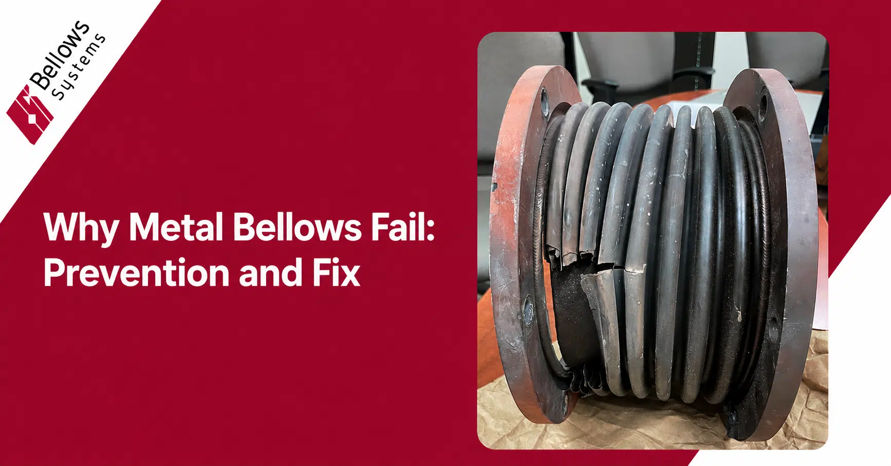
Cracks developing at the convolution roots (the inner diameter of the fold) or crowns (the outer diameter), often propagating through the wall thickness over time. The bellows may begin leaking before the crack is visible from the outside.
What Causes It
Fatigue cracking is the most common bellows failure mode, and it almost always traces back to one of three root causes: the bellows was underspecified for the actual cycle count, the movement was larger than the rated movement, or both happened simultaneously.
Every convolution flex cycle introduces stress at the convolution geometry. When the cumulative stress exceeds the material’s fatigue limit — either because the per-cycle stress was too high or because the part was cycled more times than it was designed for — cracks initiate and grow.
How to Prevent It
- Specify cycle life requirement accurately before ordering — account for startup/shutdown frequency, pressure cycling, and thermal cycling
- Do not exceed the rated movement of the bellows element — over-travel is the single fastest path to fatigue failure
- Use multi-ply bellows for high-cycle applications — thinner individual plies reduce per-cycle stress
- Include movement control hardware (tie rods, limit rods, guides) to prevent accidental over-extension
Failure Mode 2: Corrosion Attack
What It Looks Like
Surface pitting, crevice corrosion at weld joints, stress corrosion cracking (SCC) in the convolution walls, or uniform wall thinning. Can be difficult to detect visually until a leak develops.
What Causes It
Material mismatch with the operating environment. The most common scenario: a standard 304SS or 316SS bellows specified into a system where chlorides are present. 300-series stainless steels are susceptible to stress corrosion cracking when exposed to chloride ions under tensile stress — and a bellows under operating pressure has plenty of tensile stress.
Other common corrosion scenarios include: external insulation under cladding trapping moisture and chlorides against the bellows OD (often called CSCC — chloride stress corrosion cracking), acidic process media attacking the bellows ID, and galvanic corrosion at the weld interface if filler material and base material aren’t matched.
How to Prevent It
- Match alloy selection to both internal media and external environment — don’t just check the process fluid
- Use Inconel 625 or Duplex stainless in chloride-rich environments
- Review insulation system design — wet insulation against stainless steel is a well-documented CSCC mechanism
- Use BSI’s chemical compatibility tool to screen your media against candidate materials
- Specify matching filler material for all bellows welds
Failure Mode 3: In-Plane Squirm (Buckling)
What It Looks Like
The bellows deflect sideways or buckles in a serpentine pattern rather than compressing uniformly. The bellows look bent or kinked, often permanently deformed.
What Causes It
In-plane squirm occurs when internal pressure creates a force that exceeds the bellows’ lateral stability limit. It’s essentially a column buckling failure — the bellows under pressure acts like a long, thin column under axial load. If the pressure is high enough or the bellows is long enough relative to its diameter, lateral instability occurs.
This is a design failure when it happens — it means the bellows was not properly designed for the operating pressure, or the pressure was higher than the specified design pressure in the field.
How to Prevent It
- Ensure the bellows is designed with adequate squirm pressure rating above the maximum operating pressure plus any surge allowance
- Use internal flow liners or external tie rod systems for long bellows elements in high-pressure service
- Do not exceed the specified operating pressure
- Request EJMA design calculations that include squirm pressure verification
Failure Mode 4: Over-Compression and End Convolution Overloading
What It Looks Like
The bellows is compressed beyond its design travel. End convolutions are permanently distorted. In severe cases the convolutions interlock or “coil bind” — full metal-to-metal contact between adjacent convolution crowns.
What Causes It
This typically happens when a bellows is installed in a piping system without proper anchoring or guiding, and thermal growth of the adjacent pipe compresses the bellows beyond its rated axial travel. It also happens when a replacement bellows is installed with incorrect pre-compression, or when the original pipe stress analysis underestimated thermal expansion.
How to Prevent It
- Install travel limit stops (limit rods) to prevent over-compression
- Verify thermal expansion calculations before installation — include coefficient of thermal expansion for the pipe material and the actual temperature differential
- Use expansion joints with external hardware (hinged, gimbal, or pressure-balanced designs) to control movement
- Check Bellows Systems’ metal expansion joint options if you need hardware-controlled movement management
Failure Mode 5: Flow-Induced Vibration and Erosion
What It Looks Like
Premature fatigue failure or wall thinning on the ID of the bellows convolutions. Often occurs in high-velocity flow systems. The failure may look similar to fatigue cracking but occurs much faster and is localized to convolution valleys rather than distributed.
What Causes It
High-velocity process media — gas, steam, or liquid — flowing through a bellows can create turbulent vortices at the convolutions. These vortices can excite resonant vibration in the convolutions (acoustic resonance) and cause rapid fatigue, or cause physical erosion of the convolution walls in liquid or two-phase flow.
How to Prevent It
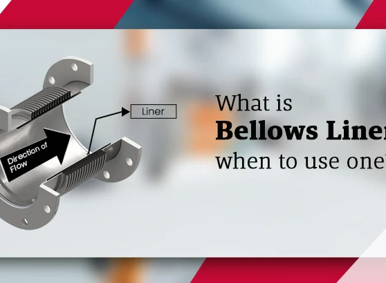
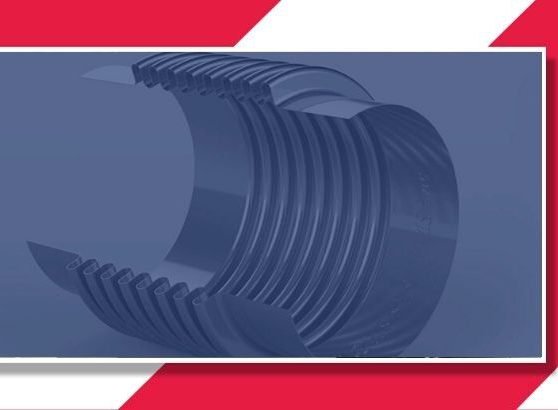
- Install an internal sleeve or flow liner to protect convolutions from direct flow impingement in high-velocity applications
- Check media velocity against bellows resonance limits — these are calculable per EJMA standards
- Use thicker wall material or multi-ply construction in high-velocity erosive service
- Ensure flow direction is consistent with liner installation (liners are directional)
Summary: Failure Mode vs. Root Cause vs. Prevention
| Failure Mode | Primary Root Cause | Key Prevention |
|---|---|---|
| Fatigue cracking | Over-travel or under-specified cycle life | Accurate cycle spec + movement limits |
| Corrosion attack | Material mismatch with environment | Correct alloy selection + compatibility check |
| In-plane squirm | Excess pressure vs. stability rating | EJMA squirm rating + tie rods |
| Over-compression | Excess thermal movement or wrong install | Limit rods + pipe stress analysis |
| Flow-erosion/vibration | High-velocity media hitting convolutions | Internal flow liner + velocity check |
The good news: every one of these failure modes is well understood, calculable, and preventable. A bellows properly designed per EJMA standards, specified with accurate operating data, and installed correctly should reach its full design life — often 20 years or more in well-managed piping systems.
Experiencing premature bellows failure? BSI’s engineers can help identify the root cause and specify a replacement that won’t repeat it. Call (800) 233-0623 or visit bellows-systems.com/get-quote
Related Resources
- Metal Expansion Joints — hinged, gimbal, and pressure-balanced designs for controlled movement
- Testing and Qualification — how BSI validates bellows before shipment
- Installation Instructions — proper installation prevents most failure modes
- Bellows Definitions — technical glossary for bellows and expansion joint terms
- EJMA Standards (External) — the authoritative standard for bellows design and failure analysis