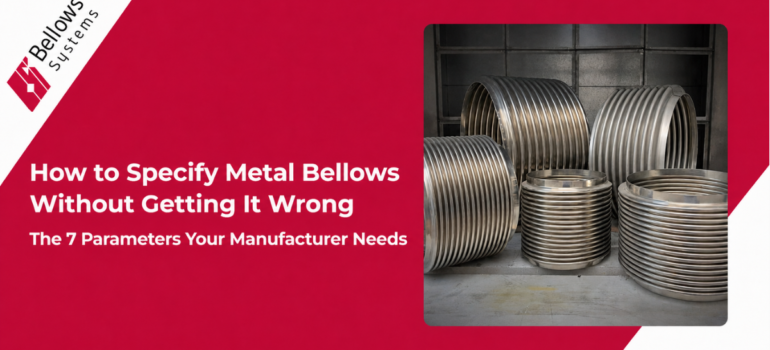
How to Specify Metal Bellows Without Getting It Wrong: The 7 Parameters Your Manufacturer Needs
Summary:
Most metal bellows RFQs that result in wrong parts, extended lead times, or re-orders trace back to incomplete specifications. Give your manufacturer these 7 parameters upfront — operating pressure, temperature range, movement requirements, cycle life, media/fluid, space envelope, and end configuration — and you’ll get a part that works from day one.
If you’ve ever placed a bellows order that came back wrong — or spent three weeks in back-and-forth emails with a manufacturer trying to establish what you actually need — you already know that bellows specification is more nuanced than it looks.
This guide gives you the complete list of information a metal bellows manufacturer needs to design and build a part that will perform in your application. Whether you’re a first-time buyer or an experienced procurement engineer switching to a new supplier, this is the specification checklist to use before you submit any RFQ.
Why Incomplete Specs Are Expensive
A bellows designed for the wrong pressure rating fails by buckling or yielding. A bellows designed for the wrong temperature range experiences creep or fatigue. A bellows designed without proper movement data gets over-cycled and fails early. A bellows with the wrong end configuration doesn’t fit the piping.
Every one of these failures results in replacement cost, downtime, and often emergency procurement at premium lead times. The investment in getting the spec right upfront is trivially small compared to the cost of getting it wrong.
The 7 Parameters Every Metal Bellows Specification Needs
Parameter 1: Operating Pressure
State the maximum operating pressure in PSI or bar, and indicate whether it’s internal pressure or external pressure (some applications, like externally pressurized expansion joints, have pressure on the outside of the bellows).
Also note any pressure cycling — if the system cycles from 0 to max pressure repeatedly, that affects fatigue life calculations. Include both the design pressure and any pressure spikes or surge conditions.
Parameter 2: Temperature Range
Provide both the minimum and maximum operating temperatures, and specify whether high-temperature exposure is continuous or cyclic. A bellows that’s at 1200°F for two hours then cools to ambient experiences very different stress conditions than one at 1200°F continuously.
Temperature range directly drives material selection — it’s the primary input for determining whether standard stainless steel grades or high-nickel alloys are required.
Parameter 3: Movement Requirements
This is the most commonly under-specified parameter — and the most consequential for fatigue life. You need to provide:
- Axial movement: compression and extension, in inches or mm
- Lateral offset (angular or parallel): in inches or mm, and the direction
- Whether movements occur simultaneously or independently
- Whether movement is cyclic (happens repeatedly) or is a one-time installation offset
If you’re unsure of the exact movement values, a thermal analysis or pipe stress analysis of your system will generate them. Bellows Systems’ engineering team can assist with piping design and stress analysis if needed.
Parameter 4: Cycle Life Requirement
How many times will the bellows be subjected to full movement, pressure cycling, or thermal cycling over its service life? This might be 50 startup/shutdown cycles per year for an industrial boiler, or 100,000 cycles per year for a pneumatic actuator.
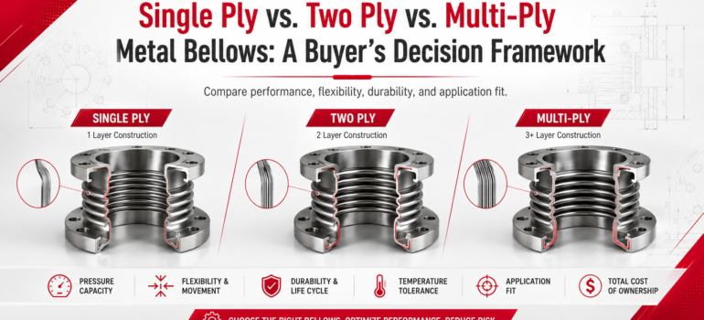
Cycle life requirement is the primary input for determining ply count, convolution geometry, and wall thickness in the bellows design. A part rated for 1,000 cycles looks and costs very different from one rated for 1,000,000 cycles.
Parameter 5: Media / Process Fluid
What are the bellows in contact with on the inside? What is it exposed to on the outside? This drives material selection and may also affect surface finish requirements.
Be specific: not just ‘gas’ but ‘natural gas with up to 200 ppm H2S.’ Not just ‘acid’ but ‘sulfuric acid at 20% concentration at 180°F.’ The difference between these details can mean the difference between 316SS and Hastelloy C-276 — and a service life of 20 years versus 2 years.
Use Bellows Systems’ chemical compatibility tool to check your process fluid against available materials.
Parameter 6: Physical Dimensions and Space Envelope
Provide:
- Bore diameter (ID) — the pipe or duct inner diameter the bellows must match
- Overall installed length — the face-to-face dimension in the piping or equipment
- Any restrictions on OD — clearance constraints from insulation, adjacent piping, or structural members
- Cross-section profile — circular, rectangular, oval, or custom shape
- Number of convolutions if specified by your design standard
Parameter 7: End Configuration
How will the bellows connect to the adjacent piping or equipment? Bellows Systems manufactures multiple end configurations:
- Standard I-cuff ends — straight tangent ends for welding into pipe
- S-cuff, T-cuff, U-cuff, V-cuff ends — various flange and attachment profiles
- Cut-at-crest or cut-at-root ends — for integration into expansion joint assemblies
- Truncated convolutions — for space-constrained installations
If the bellows will be assembled into a larger expansion joint, flanged connector, or OEM device, include a sketch or drawing of the assembly interface. This prevents the single most common misfit error in bellows procurement.
Optional But Highly Useful: Additional Specification Details
| Additional Item | Why It Matters |
|---|---|
| Design standard (EJMA, ASME, ASTM) | Determines documentation and testing requirements |
| Material certifications required (MTR, CMTR) | Required for aerospace, nuclear, and some O&G applications |
| NDE requirements (X-ray, dye penetrant, hydro test) | Defines quality inspection deliverables |
| Quantity and delivery requirement | Affects whether stock elements or full custom manufacture is used |
| Environment (indoor, outdoor, marine, subsea) | May affect surface treatment or protective coatings |
| Relevant drawing or model file | Speeds up engineering review dramatically |
The RFQ Template: What to Send
When you submit an RFQ to Bellows Systems, you can use this structure:
- Application description — one sentence on what the bellows is for
- Operating pressure (max, design, any surge)
- Temperature range (min, max, continuous vs. cyclic)
- Movement: axial (compression/extension), lateral, angular
- Cycle life requirement
- Media in contact (inside and outside)
- Physical dimensions: ID, overall length, OD envelope
- End configuration (or reference drawing)
- Quantity and required delivery date
- Any applicable design standards or certifications
If you have a drawing or model, attach it. If you don’t, that’s fine — BSI’s engineering team can develop one as part of the quoting process.
Ready to submit an RFQ? Use the Bellows Systems Get Quote form or call (800) 233-0623 — bellows-systems.com/get-quote
Related Resources
- Metal Bellows Product Overview — full product range
- Metal Expansion Joints — when bellows elements are assembled into expansion joint systems
- Custom Engineering Services — EJMA/ASME design and pipe stress analysis
- Bellows FAQ — common specification questions answered
- Piping Design Guide — piping system bellows selection guidance
- ASME B31.3 Process Piping Standard (External) — standard for process piping design

 Bellows Systems is a single source for industry’s most complete line of