How to specify Metal Bellows Without Getting it wrong guide

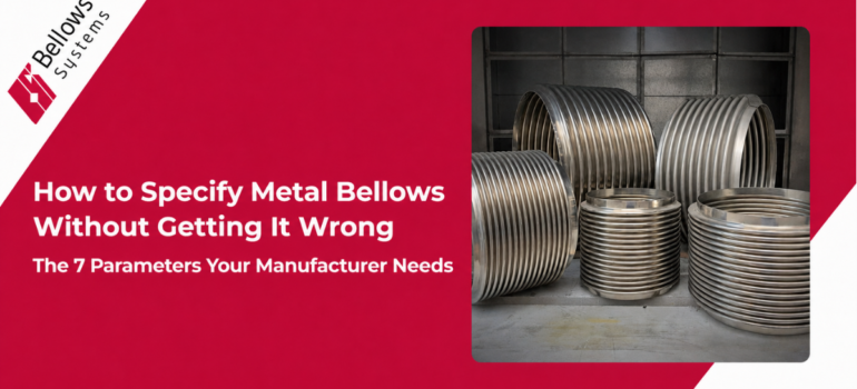
How to Specify Metal Bellows Without Getting It Wrong: The 7 Parameters Your Manufacturer Needs

Summary:

Most metal bellows RFQs that result in wrong parts, extended lead times, or re-orders trace back to incomplete specifications. Give your manufacturer these 7 parameters upfront — operating pressure, temperature range, movement requirements, cycle life, media/fluid, space envelope, and end configuration — and you’ll get a part that works from day one.

If you’ve ever placed a bellows order that came back wrong — or spent three weeks in back-and-forth emails with a manufacturer trying to establish what you actually need — you already know that bellows specification is more nuanced than it looks.

This guide gives you the complete list of information a metal bellows manufacturer needs to design and build a part that will perform in your application. Whether you’re a first-time buyer or an experienced procurement engineer switching to a new supplier, this is the specification checklist to use before you submit any RFQ.

Why Incomplete Specs Are Expensive

A bellows designed for the wrong pressure rating fails by buckling or yielding. A bellows designed for the wrong temperature range experiences creep or fatigue. A bellows designed without proper movement data gets over-cycled and fails early. A bellows with the wrong end configuration doesn’t fit the piping.

Every one of these failures results in replacement cost, downtime, and often emergency procurement at premium lead times. The investment in getting the spec right upfront is trivially small compared to the cost of getting it wrong.

The 7 Parameters Every Metal Bellows Specification Needs

Parameter 1: Operating Pressure

State the maximum operating pressure in PSI or bar, and indicate whether it’s internal pressure or external pressure (some applications, like externally pressurized expansion joints, have pressure on the outside of the bellows).

Also note any pressure cycling — if the system cycles from 0 to max pressure repeatedly, that affects fatigue life calculations. Include both the design pressure and any pressure spikes or surge conditions.

Parameter 2: Temperature Range

Provide both the minimum and maximum operating temperatures, and specify whether high-temperature exposure is continuous or cyclic. A bellows that’s at 1200°F for two hours then cools to ambient experiences very different stress conditions than one at 1200°F continuously.

Temperature range directly drives material selection — it’s the primary input for determining whether standard stainless steel grades or high-nickel alloys are required.

Parameter 3: Movement Requirements

This is the most commonly under-specified parameter — and the most consequential for fatigue life. You need to provide:

  • Axial movement: compression and extension, in inches or mm
  • Lateral offset (angular or parallel): in inches or mm, and the direction
  • Whether movements occur simultaneously or independently
  • Whether movement is cyclic (happens repeatedly) or is a one-time installation offset

If you’re unsure of the exact movement values, a thermal analysis or pipe stress analysis of your system will generate them. Bellows Systems’ engineering team can assist with piping design and stress analysis if needed.

Parameter 4: Cycle Life Requirement

How many times will the bellows be subjected to full movement, pressure cycling, or thermal cycling over its service life? This might be 50 startup/shutdown cycles per year for an industrial boiler, or 100,000 cycles per year for a pneumatic actuator.

Cycle life requirement is the primary input for determining ply count, convolution geometry, and wall thickness in the bellows design. A part rated for 1,000 cycles looks and costs very different from one rated for 1,000,000 cycles.

Parameter 5: Media / Process Fluid

What are the bellows in contact with on the inside? What is it exposed to on the outside? This drives material selection and may also affect surface finish requirements.

Be specific: not just ‘gas’ but ‘natural gas with up to 200 ppm H2S.’ Not just ‘acid’ but ‘sulfuric acid at 20% concentration at 180°F.’ The difference between these details can mean the difference between 316SS and Hastelloy C-276 — and a service life of 20 years versus 2 years.

Use Bellows Systems’ chemical compatibility tool to check your process fluid against available materials.

Parameter 6: Physical Dimensions and Space Envelope

Provide:

  • Bore diameter (ID) — the pipe or duct inner diameter the bellows must match
  • Overall installed length — the face-to-face dimension in the piping or equipment
  • Any restrictions on OD — clearance constraints from insulation, adjacent piping, or structural members
  • Cross-section profile — circular, rectangular, oval, or custom shape
  • Number of convolutions if specified by your design standard

Parameter 7: End Configuration

How will the bellows connect to the adjacent piping or equipment? Bellows Systems manufactures multiple end configurations:

  • Standard I-cuff ends — straight tangent ends for welding into pipe
  • S-cuff, T-cuff, U-cuff, V-cuff ends — various flange and attachment profiles
  • Cut-at-crest or cut-at-root ends — for integration into expansion joint assemblies
  • Truncated convolutions — for space-constrained installations

If the bellows will be assembled into a larger expansion joint, flanged connector, or OEM device, include a sketch or drawing of the assembly interface. This prevents the single most common misfit error in bellows procurement.

Optional But Highly Useful: Additional Specification Details

Additional Item Why It Matters
Design standard (EJMA, ASME, ASTM) Determines documentation and testing requirements
Material certifications required (MTR, CMTR) Required for aerospace, nuclear, and some O&G applications
NDE requirements (X-ray, dye penetrant, hydro test) Defines quality inspection deliverables
Quantity and delivery requirement Affects whether stock elements or full custom manufacture is used
Environment (indoor, outdoor, marine, subsea) May affect surface treatment or protective coatings
Relevant drawing or model file Speeds up engineering review dramatically

The RFQ Template: What to Send

When you submit an RFQ to Bellows Systems, you can use this structure:

  • Application description — one sentence on what the bellows is for
  • Operating pressure (max, design, any surge)
  • Temperature range (min, max, continuous vs. cyclic)
  • Movement: axial (compression/extension), lateral, angular
  • Cycle life requirement
  • Media in contact (inside and outside)
  • Physical dimensions: ID, overall length, OD envelope
  • End configuration (or reference drawing)
  • Quantity and required delivery date
  • Any applicable design standards or certifications

If you have a drawing or model, attach it. If you don’t, that’s fine — BSI’s engineering team can develop one as part of the quoting process.

Ready to submit an RFQ? Use the Bellows Systems Get Quote form or call (800) 233-0623 — bellows-systems.com/get-quote

Related Resources

Read More
Single Ply vs. Two Ply vs. Multi-Ply Metal Bellows

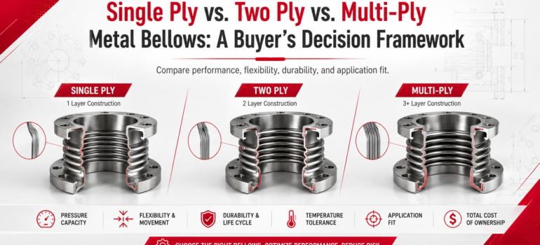
Single Ply vs. Two Ply vs. Multi-Ply Metal Bellows: A Buyer’s Decision Framework

When you’re specifying a metal bellows, one of the first decisions you’ll face is how many plies — layers of material — your bellows element needs. It seems like a simple technical choice, but it has significant consequences for cost, service life, spring rate, pressure capacity, and fatigue performance.

This guide breaks down exactly what each ply configuration offers, where each falls short, and how to match the right ply count to your actual application.

What Does 'Ply' Mean in Metal Bellows?

In metal bellows manufacturing, a ‘ply’ refers to a single layer of material formed into the convolution profile of the bellows. A single-ply bellows has one layer. A two-ply bellows has two concentric layers formed together. A multi-ply bellows has three or more layers.

The plies are formed together as a unit — they move together as the bellows compresses, extends, or deflects laterally. The key differences between ply configurations show up in pressure capacity, spring rate (the force required to move the bellows), cycle life, and manufacturing cost.

Single Ply Bellows

What It Is

A single-ply bellows is formed from a single tube of material. The convolutions are formed using mechanical punch forming or hydroforming, creating a flexible element that can absorb movement in axial, lateral, or angular directions.

What It Does Well

  • Lowest spring rate — requires the least force to move, minimizing loads on adjacent piping or equipment
  • Best flexibility for a given convolution geometry
  • Most cost-effective option for straightforward applications
  • Easiest to manufacture in a wide range of sizes, from very small OEM components up to large pipe sizes
  • Well-suited for small axial movements in low-to-moderate pressure applications

Where It Falls Short

  • Lower pressure capacity compared to multi-ply at the same wall thickness
  • More susceptible to fatigue failure under high cycle counts
  • Not recommended for applications with large movements, high pressures, or demanding thermal cycling

Best Applications for Single Ply

  • Mechanical seals and actuators where low spring rate is critical
  • Fluid management components: accumulators, volume compensators
  • Low-pressure piping expansion joints with small movements
  • OEM components in instruments and precision equipment

Learn more about our single ply options: See the Bellows Systems Single Ply Bellows page.

Two Ply Bellows (Pipe Bellows)

What It Is

A two-ply bellows uses two concentric layers of thinner material formed together into the convolution profile. The two plies work together mechanically, and the combined structure behaves differently from simply doubling the wall thickness.

What It Does Well

  • Better pressure capacity than single ply at the same overall diameter
  • Improved fatigue life — the load is distributed across two layers, reducing peak stress at any single point
  • Good spring rate balance — stiffer than single ply but still flexible enough for piping applications
  • Wider operating range — handles larger movements than comparable single-ply elements
  • Better redundancy — if a pinhole leak develops in one ply, the second ply continues to contain the media

Where It Falls Short

  • Higher spring rate than single ply — can introduce more load into the piping system
  • More expensive than single ply due to additional material and forming operations
  • Not rated for the highest-pressure or extreme temperature applications

Best Applications for Two Ply

  • Process piping expansion joints in chemical plants, refineries, and power generation
  • Gas and liquid piping systems with moderate pressure and temperature
  • Applications requiring extended cycle life without the cost premium of multi-ply
  • Where redundancy against through-wall failure adds safety value

Multi-Ply Bellows

What It Is

Multi-ply bellows use three or more layers of material — with each ply typically thinner than what would be used in a single or two-ply design. Bellows Systems specializes in multi-ply bellows with high cycle life, using state-of-the-art seam welded tube technology.

What It Does Well

  • Highest pressure capacity of any bellows configuration at a given diameter
  • Engineered for demanding cycle life — used in applications with thousands of thermal or pressure cycles
  • Thinner individual plies mean lower stress per ply, extending fatigue life significantly
  • Can be designed to specific spring rate, cycle life, and pressure targets
  • Essential for high-temperature, high-pressure, and high-vibration environments

Where It Falls Short

  • Higher cost due to complex manufacturing and precision material requirements
  • More technically demanding to specify — requires engineering input on ply count, thickness, and convolution geometry
  • Not necessary (and therefore overcost) for simple, low-demand applications

Best Applications for Multi-Ply

  • Engine exhaust systems (Caterpillar, Waukesha, Solar Gas Turbines) with continuous thermal cycling
  • Aerospace and defense applications requiring certified fatigue life
  • Subsea and high-pressure oil and gas applications
  • Power generation systems with startup/shutdown cycle requirements
  • Any application where EJMA design calculations must be documented

Side-by-Side Comparison

Factor Single Ply Two Ply Multi-Ply
Pressure Capacity Moderate Good Highest
Cycle Life Basic Good Engineered (highest)
Spring Rate Lowest Moderate Higher (tunable)
Movement Range Small Moderate Application-specific
Cost Lowest Mid Higher
Leak Redundancy None One backup ply Multiple backup plies
Engineering Complexity Low Moderate High
Best Fit OEM, instruments, seals Process piping, general industrial Exhaust, high-P/T, aerospace

The Decision Shortcut

If you answer yes to any of the following, step up to multi-ply:

  • Operating temperature above 900°F (482°C) continuously
  • More than 5,000 thermal or pressure cycles per year
  • Operating pressure above the single or two-ply catalog limit for your bore size
  • Application is in aerospace, defense, or a safety-critical system requiring documented fatigue life
  • Media leakage would be a safety or environmental incident

If none of those apply, two-ply is usually the right balance of performance and cost for process piping and industrial applications. Single ply is correct for low-pressure, low-cycle OEM components.

Not sure which ply configuration fits your application? Our engineers will tell you — (800) 233-0623 | bellows-systems.com/get-quote

Related Resources

Read More
Metal Bellows Material Selection Guide

Metal Bellows Material Selection Guide: Stainless Steel vs. Inconel vs. Hastelloy

Material selection is the single decision in metal bellows specification that has the most catastrophic failure modes when wrong. A bellows can be perfectly designed, correctly formed, and precisely welded — and still fail in six months if the alloy was chosen to match the budget rather than the operating environment.

This guide walks through the most common material options available for custom metal bellows, what each one does well, where each one fails, and how to match material to your specific application. It’s written for procurement engineers, plant designers, and OEM specifiers who need to make this decision with confidence.

The Core Question: What Is Your Bellows Being Asked to Survive?

Before you look at material specs, answer these four questions:

  • What is the maximum operating temperature — and is it continuous or cyclic?
  • What media (fluid, gas, or slurry) is in contact with the bellows?
  • What external environment is the bellows exposed to (marine air, chemical splash, oxidizing atmosphere)?
  • How many thermal or pressure cycles will the bellows see per year?

Your answers to those four questions will narrow your material choice down to one or two options in almost every case.

Austenitic Stainless Steels: The Starting Point

304 SS and 304L SS

304SS is the most widely used bellows material in industrial applications. It offers good corrosion resistance in most mild environments, is easily formed and welded, and is cost-effective.

Use 304SS when: Your operating temperature is below 800°F (427°C), your media is non-chloride, and you don’t have sour gas or highly acidic conditions.

Avoid 304SS when: Chloride exposure is present (coastal environments, saltwater, certain process chemicals) — 304SS is susceptible to stress corrosion cracking under chloride attack.

304L is the low-carbon variant, preferred when welding is involved to prevent sensitization (carbide precipitation at grain boundaries that weakens corrosion resistance).

316 SS and 316L SS

316SS adds molybdenum to the 304 composition, significantly improving resistance to chloride pitting and crevice corrosion. It’s the standard upgrade from 304SS for chemical processing, marine, and offshore environments.

Use 316SS when: Chloride exposure is moderate, operating temperatures are below 870°F (465°C) continuous, and your media includes dilute acids or saltwater.

316L is the preferred variant for welded fabrication in corrosive service.

321 SS

321SS is stabilized with titanium, which prevents sensitization during high-temperature service — making it the standard choice for elevated temperature applications like exhaust systems and fired heaters.

Use 321SS when: Operating temperatures are between 800°F and 1500°F (427–816°C) and the bellows will spend extended time at high temperature rather than cycling through it.

347 SS

347SS is stabilized with niobium (columbium), giving it slightly better high-temperature strength than 321SS. It’s used in aerospace and power generation applications where creep resistance at elevated temperatures is important.

310 SS

310SS has the highest chromium and nickel content of the standard austenitic grades, making it the best choice for extreme oxidation resistance at very high temperatures — up to 2100°F (1149°C) in intermittent service.

Nickel Alloys: When Stainless Steel Isn't Enough

Inconel 600

Good high-temperature oxidation resistance and resistance to stress corrosion cracking in caustic environments. Used in chemical processing and heat treating applications. Temperature range up to approximately 2000°F (1093°C).

Inconel 601

Higher aluminum content gives Inconel 601 outstanding resistance to oxidation and carburization at very high temperatures. Used in furnace components, gas turbine exhaust, and industrial heating systems.

Inconel 625

The workhorse of demanding bellows applications. Inconel 625 combines high strength, excellent fabricability, and outstanding corrosion resistance across a wide temperature range. It’s particularly valued for its resistance to pitting, crevice corrosion, and stress corrosion cracking.

Use Inconel 625 when: You have combined high temperature and aggressive corrosion conditions, subsea or sour gas applications, or aerospace and power generation service where fatigue life under thermal cycling is critical.

Incoloy 800 and 800H

Incoloy 800 (and the higher-carbon 800H variant) offers excellent resistance to oxidation and carburization and good creep strength at elevated temperatures. It’s commonly used in heat exchangers, petrochemical furnaces, and power generation systems.

Incoloy 825

Incoloy 825 adds molybdenum and copper to provide exceptional resistance to reducing acids, particularly sulfuric and phosphoric acid. It’s the standard choice for phosphoric acid service and sulfur-containing environments.

Monel 400

Monel 400 is a nickel-copper alloy with outstanding resistance to seawater, hydrofluoric acid, and alkalis. It’s the default material for marine bellows in direct seawater contact and for hydrofluoric acid service.

Hastelloy: For the Harshest Chemical Environments

Hastelloy alloys — primarily C-276 and C-22 — are the most corrosion-resistant nickel alloys available for bellows fabrication. They handle oxidizing and reducing conditions that would rapidly attack stainless steels and even most other nickel alloys.

Use Hastelloy C-276 when: Your process involves wet chlorine, chlorine dioxide, hypochlorites, sulfuric acid, or mixed acid environments. It’s widely used in chemical processing, pharmaceutical, and waste treatment applications.

Material Selection Summary Table

Material Max Temp (F) Key Strength Avoid When Typical Application
304 / 304L SS 800°F Cost-effective, general use Chloride exposure General industrial, HVAC
316 / 316L SS 870°F Chloride + corrosion resistance High-temp continuous service Chemical, marine, offshore
321 SS 1500°F High-temp stability, stabilized Chloride environments Exhaust systems, fired heaters
347 SS 1500°F Better creep than 321SS Chloride environments Aerospace, power gen
310 SS 2100°F Extreme oxidation resistance Aqueous corrosion Furnaces, fired heaters
Inconel 625 1800°F Combined high-temp + corrosion Budget-limited projects Subsea, sour gas, aerospace
Inconel 600/601 2000°F Oxidation + carburization Reducing acid service Gas turbine exhaust, furnaces
Incoloy 825 1000°F Reducing acid resistance High-temp service Phosphoric acid, sulfur environments
Monel 400 1000°F Seawater + HF acid resistance Oxidizing conditions Marine, HF acid service
Hastelloy C-276 1900°F Broadest chemical resistance Cost-sensitive projects Chemical processing, chlorine service

Special Materials Available From Bellows Systems

In addition to the alloys listed above, Bellows Systems manufactures bellows in Copper, Titanium, Aluminum, and Tantalum for specialized applications. Titanium is increasingly specified for aerospace and subsea applications where weight and corrosion resistance are both critical. Tantalum is used in the most chemically aggressive environments — concentrated hydrochloric acid, fuming nitric acid — where no other material survives.

One More Thing: The Weld Material Matters Too

A bellows is only as corrosion-resistant as its weakest point — and the weld seam is often that point. Bellows Systems maintains over 150 qualified welding procedures across different material combinations, with AWS-certified welders who specialize in thin-wall alloy fabrication. When you specify an exotic alloy for your bellows, make sure your manufacturer can actually weld it properly.

Not sure which material is right for your application? Our engineering team has been specifying bellows alloys for 40 years. Call (800) 233-0623 or visit bellows-systems.com/get-quote

Related Resources

Read More
Why Metal Bellows Fail: Prevention and Fix

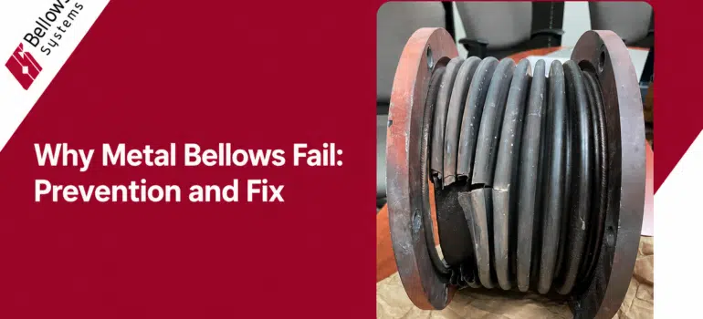
Metal Bellows Failure Analysis: The 5 Most Common Failure Modes and How to Prevent Them

Summary

Fatigue cracking, corrosion, in-plane squirm, over-compression, and flow-induced vibration erosion account for the vast majority of premature metal bellows failures. Every one of them is preventable — at the design stage, the specification stage, or the installation stage. Most failures are not manufacturing defects. They are spec or installation errors.

A metal bellows that fails prematurely isn’t just an inconvenience — it’s a forced outage, a potential safety incident, and an unbudgeted emergency repair. For plant operators and maintenance engineers, understanding why bellows fail is the most direct path to preventing the next one from failing.

This article covers the five most common metal bellows failure modes, what causes each one, how to identify them, and what you can do at the specification and installation stage to prevent them.

Failure Mode 1: Fatigue Cracking

What It Looks Like

Cracks developing at the convolution roots (the inner diameter of the fold) or crowns (the outer diameter), often propagating through the wall thickness over time. The bellows may begin leaking before the crack is visible from the outside.

What Causes It

Fatigue cracking is the most common bellows failure mode, and it almost always traces back to one of three root causes: the bellows was underspecified for the actual cycle count, the movement was larger than the rated movement, or both happened simultaneously.

Every convolution flex cycle introduces stress at the convolution geometry. When the cumulative stress exceeds the material’s fatigue limit — either because the per-cycle stress was too high or because the part was cycled more times than it was designed for — cracks initiate and grow.

How to Prevent It

  • Specify cycle life requirement accurately before ordering — account for startup/shutdown frequency, pressure cycling, and thermal cycling
  • Do not exceed the rated movement of the bellows element — over-travel is the single fastest path to fatigue failure
  • Use multi-ply bellows for high-cycle applications — thinner individual plies reduce per-cycle stress
  • Include movement control hardware (tie rods, limit rods, guides) to prevent accidental over-extension

Failure Mode 2: Corrosion Attack

What It Looks Like

Surface pitting, crevice corrosion at weld joints, stress corrosion cracking (SCC) in the convolution walls, or uniform wall thinning. Can be difficult to detect visually until a leak develops.

What Causes It

Material mismatch with the operating environment. The most common scenario: a standard 304SS or 316SS bellows specified into a system where chlorides are present. 300-series stainless steels are susceptible to stress corrosion cracking when exposed to chloride ions under tensile stress — and a bellows under operating pressure has plenty of tensile stress.

Other common corrosion scenarios include: external insulation under cladding trapping moisture and chlorides against the bellows OD (often called CSCC — chloride stress corrosion cracking), acidic process media attacking the bellows ID, and galvanic corrosion at the weld interface if filler material and base material aren’t matched.

How to Prevent It

  • Match alloy selection to both internal media and external environment — don’t just check the process fluid
  • Use Inconel 625 or Duplex stainless in chloride-rich environments
  • Review insulation system design — wet insulation against stainless steel is a well-documented CSCC mechanism
  • Use BSI’s chemical compatibility tool to screen your media against candidate materials
  • Specify matching filler material for all bellows welds

Failure Mode 3: In-Plane Squirm (Buckling)

What It Looks Like

The bellows deflect sideways or buckles in a serpentine pattern rather than compressing uniformly. The bellows look bent or kinked, often permanently deformed.

What Causes It

In-plane squirm occurs when internal pressure creates a force that exceeds the bellows’ lateral stability limit. It’s essentially a column buckling failure — the bellows under pressure acts like a long, thin column under axial load. If the pressure is high enough or the bellows is long enough relative to its diameter, lateral instability occurs.

This is a design failure when it happens — it means the bellows was not properly designed for the operating pressure, or the pressure was higher than the specified design pressure in the field.

How to Prevent It

  • Ensure the bellows is designed with adequate squirm pressure rating above the maximum operating pressure plus any surge allowance
  • Use internal flow liners or external tie rod systems for long bellows elements in high-pressure service
  • Do not exceed the specified operating pressure
  • Request EJMA design calculations that include squirm pressure verification

Failure Mode 4: Over-Compression and End Convolution Overloading

What It Looks Like

The bellows is compressed beyond its design travel. End convolutions are permanently distorted. In severe cases the convolutions interlock or “coil bind” — full metal-to-metal contact between adjacent convolution crowns.

What Causes It

This typically happens when a bellows is installed in a piping system without proper anchoring or guiding, and thermal growth of the adjacent pipe compresses the bellows beyond its rated axial travel. It also happens when a replacement bellows is installed with incorrect pre-compression, or when the original pipe stress analysis underestimated thermal expansion.

How to Prevent It

  • Install travel limit stops (limit rods) to prevent over-compression
  • Verify thermal expansion calculations before installation — include coefficient of thermal expansion for the pipe material and the actual temperature differential
  • Use expansion joints with external hardware (hinged, gimbal, or pressure-balanced designs) to control movement
  • Check Bellows Systems’ metal expansion joint options if you need hardware-controlled movement management

Failure Mode 5: Flow-Induced Vibration and Erosion

What It Looks Like

Premature fatigue failure or wall thinning on the ID of the bellows convolutions. Often occurs in high-velocity flow systems. The failure may look similar to fatigue cracking but occurs much faster and is localized to convolution valleys rather than distributed.

What Causes It

High-velocity process media — gas, steam, or liquid — flowing through a bellows can create turbulent vortices at the convolutions. These vortices can excite resonant vibration in the convolutions (acoustic resonance) and cause rapid fatigue, or cause physical erosion of the convolution walls in liquid or two-phase flow.

How to Prevent It

  • Install an internal sleeve or flow liner to protect convolutions from direct flow impingement in high-velocity applications
  • Check media velocity against bellows resonance limits — these are calculable per EJMA standards
  • Use thicker wall material or multi-ply construction in high-velocity erosive service
  • Ensure flow direction is consistent with liner installation (liners are directional)

Summary: Failure Mode vs. Root Cause vs. Prevention

Failure Mode Primary Root Cause Key Prevention
Fatigue cracking Over-travel or under-specified cycle life Accurate cycle spec + movement limits
Corrosion attack Material mismatch with environment Correct alloy selection + compatibility check
In-plane squirm Excess pressure vs. stability rating EJMA squirm rating + tie rods
Over-compression Excess thermal movement or wrong install Limit rods + pipe stress analysis
Flow-erosion/vibration High-velocity media hitting convolutions Internal flow liner + velocity check

The good news: every one of these failure modes is well understood, calculable, and preventable. A bellows properly designed per EJMA standards, specified with accurate operating data, and installed correctly should reach its full design life — often 20 years or more in well-managed piping systems.

Experiencing premature bellows failure? BSI’s engineers can help identify the root cause and specify a replacement that won’t repeat it. Call (800) 233-0623 or visit bellows-systems.com/get-quote

Related Resources

Read More
The Aerospace Bellows Procurement Checklist - Bellows Systems

The Aerospace Procurement Checklist: AS9100 & NADCAP Compliance in Bellows Manufacturing

In the aerospace industry, the margin for error isn’t just slim—it is non-existent. When a commercial jet is at 35,000 feet or a launch vehicle is exiting the atmosphere, the integrity of every single component is a matter of mission success and human safety.

For procurement professionals and engineers, selecting a manufacturer for aerospace application isn’t just about finding a part that fits a drawing; it’s about finding a partner that understands the gravity of risk mitigation. At Bellows Systems, our commitment to excellence is anchored in two critical pillars: AS9100 Rev D and NADCAP compliance.

Here is your essential procurement checklist for ensuring quality and supply chain reliability in aerospace manufacturing.

1. The Gold Standard: AS9100 Rev D Certification

The necessity of AS9100 Rev D certification cannot be overstated. While ISO 9001 provides a solid baseline for quality management, AS9100 adds layers of rigorous requirements specifically designed for the aerospace and defense sectors.

  • Why it matters: AS9100 Rev D forces a proactive approach to risk. It requires manufacturers to identify potential “what-if” scenarios throughout the production cycle—from material sourcing to final expansion joint testing.
  • The Bellows Systems Advantage: Our AS9100-certified processes ensure that every bellows we produce has a “birth certificate.” We maintain full traceability of materials, ensuring that what you receive is exactly what was engineered for your Aerospace Applications.

2. NADCAP: Mastery of Special Processes

While AS9100 governs quality management, NADCAP (National Aerospace and Defense Contractors Accreditation Program) focuses on the technical execution of “special processes.” In bellows manufacturing, this typically involves:

  • Precision Welding: Ensuring the longitudinal and circumferential welds of thin-gauge alloys meet aerospace standards. Bellows Systems is NADCAP accredited for both longitudinal seam welding (GTAW fusion welding) per AWS D17.1 and resistance seam welding (RSEW) per AWS D17.2. Our in-house metallurgical lab is fully certified to perform pre and post macros sections for RSEW per Class A requirements.
  • Non-Destructive Testing (NDT): Utilizing methods like Fluorescent Penetrant Inspection (FPI) or X-ray to detect microscopic flaws in the bellows membrane.
  • Heat Treating: Managing the grain structure of high-nickel alloys like Inconel® to ensure durability under extreme thermal cycling.

3. Supply Chain Reliability & Material Integrity

Aerospace bellows often operate in extreme environments—handling cryogenic fuels or high-temperature exhaust. Supply chain reliability starts with the raw material. A compliant manufacturer must demonstrate:

  • Conflict-Free Sourcing: Along with our supply chain partners, we source and stock both local and DFARS compliant materials as needed.
  • Counterfeit Part Prevention: Rigorous verification of Mill Test Reports (MTRs) to ensure material chemistry matches the specification exactly.
  • Capacity Planning: The ability to meet lead times without compromising the quality of the special processes mentioned above, specifically regarding Aerospace Industry.

4. Risk Mitigation Through Engineering

Risk mitigation isn’t just about checking boxes; it’s about design. At Bellows Systems, we utilize advanced EJMA (Expansion Joint Manufacturers Association) calculations and Finite Element Analysis (FEA) to predict how a bellows will behave under intense pressure and vibration.

Key Compliance Metric AS9100 Rev D Requirement Bellows Systems Standard
Risk Management Documented risk registers Integrated PFMEA (Process Failure Mode and Effects Analysis)
Traceability Material origin tracking 100% digital traceability from melt to shipment
Product Safety Emphasis on “Critical Items” Specialized handling for thin-wall aerospace components

Conclusion: Building Trust in Every Convolution

Procuring bellows for aerospace applications is a high-stakes responsibility. By prioritizing partners who hold AS9100 Rev D and follow NADCAP guidelines, you aren’t just buying a component; you are investing in a fail-safe system.

At Bellows Systems, our certifications are more than just plaques on the wall—they are the framework of our culture. We invite you to audit our processes and see how our rigorous quality standards can provide the peace of mind your next project demands.

Read More
Bellows Design for Cryogenic Temperature Applications

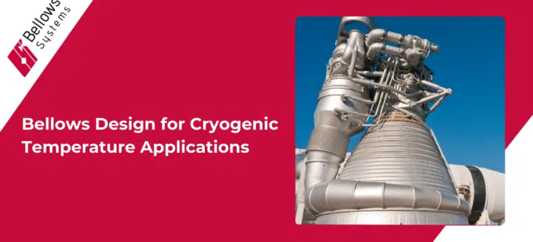
Bellows Design for Cryogenic Temperature Applications

When it comes to cryogenic temperature applications, the design and material selection for bellows become significantly more complex. Below we explore the key differences between bellows designed for cryogenic temperatures and those used in more standard conditions.

Material Selection:

Applications are generally considered “cryogenic” if operating temperatures are below -150°C (-238°F). Therefore, expansion joints must be constructed from materials that can maintain their mechanical properties at such low temperatures. Stainless steel is commonly used due to its ability to retain strength, ductility, and fatigue resistance at cryogenic temperatures. Special alloys such as Inconel or Hastelloy may also be used for their superior performance in extreme conditions, especially when coupled with high-pressure applications and/or corrosive working media.

Design Considerations:

Require additional considerations for absorbing thermal movement of a piping system, as the expansion joints’ surrounding components undergo thermal contraction at cryogenic temperatures. For applications that require minimal heat transfer between the expansion joint and its surroundings, multi-layer insulation is often included as well as special sealing techniques to minimize heat ingress, prevent thermal stress, and maintain the low-temperature environment.

Applications:

These joints are commonly seen in industries dealing with liquefied gases, such as LNG (liquefied natural gas) transport and storage, aerospace, and medical applications involving liquid nitrogen. 

Conclusion:

The design of bellows for cryogenic temperature applications involves specialized materials, advanced design techniques, careful engineering validation, and often rigorous testing to ensure they can withstand extreme conditions. These differences are crucial for maintaining the integrity and safety of systems operating at cryogenic temperatures, highlighting the importance of tailored engineering solutions for such demanding applications.

Read More
bellows expansion joint for aerospace

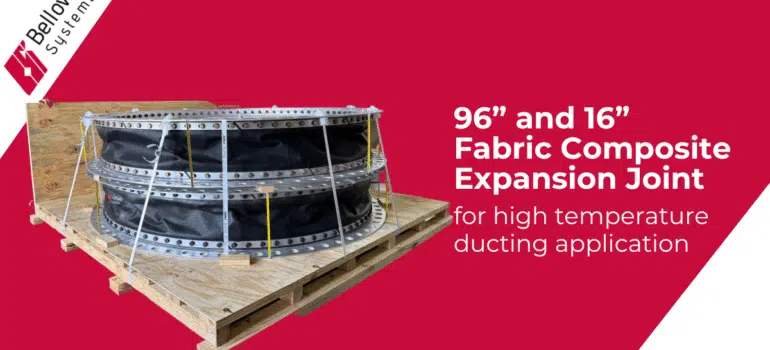
Supplying Fabric Expansion Joints for Aerospace Research Center in USA

Fabric expansion joints play a critical role in managing movement, vibration, and thermal stresses in large-scale duct systems. But when it comes to aerospace research environments, the complexity of application increases significantly. These joints must perform reliably under high temperatures, support system flexibility during propulsion testing, and maintain integrity over multiple thermal cycles.

This article explores how Bellows Systems, Inc. engineered and supplied large-diameter fabric expansion joints for an advanced aerospace research facility in the United States, addressing unique technical challenges that standard components couldn’t meet.

Engineering Requirements in Aerospace Research

Unlike traditional process plants, aerospace research centers operate under extreme test conditions that simulate real-world propulsion scenarios. The duct systems in such facilities are subject to:

  • Rapid and repeated thermal cycling
  • High-velocity airflow and turbulence
  • Vibration and mechanical movement
  • Precise dimensional constraints

To handle these variables, expansion joints must be custom-engineered for high temperature performance, movement compensation, and longevity — while still integrating seamlessly into existing system layouts.

Project Scope and Component Details

Bellows Systems was tasked with designing fabric expansion joints that could operate under such stringent demands. The components supplied included:

  • Two round fabric expansion joints
    – 96 inches in diameter
    – 18 inches in overall length
  • One round fabric expansion joint
    – 16 inches in diameter
    – 24 inches in overall length

Design and Material Considerations

The success of a fabric expansion joint in aerospace environments depends heavily on material selection and movement design.

  • High-temperature fabrics were chosen to withstand intense heat generated during test runs.
  • The multi-layer structure helped isolate vibrations and reduce thermal transmission.
  • The joints were designed to accommodate axial, lateral, and angular movements, ensuring minimal stress on adjoining ducting systems.

In addition to mechanical function, these joints needed to meet tight installation tolerances, making dimensional accuracy and fastening system integrity essential.

Performance and Outcome

Following delivery and installation, the fabric expansion joints were integrated into the research facility’s test system. They performed reliably under multiple test cycles, maintaining structural integrity, eliminating leakage, and absorbing system movements as intended.

By choosing a tailored solution rather than standard catalog joints, the facility was able to ensure:

  • Greater protection for test infrastructure
  • Reduced maintenance needs
  • Extended service life of connected equipment
  • Reliable operation in data-sensitive test environments

Final Thoughts

Supplying expansion joints for aerospace research facilities requires a deep understanding of materials, motion, and thermal dynamics. This project reflects how Bellows Systems, Inc. applies engineering expertise to deliver precision-crafted expansion solutions for highly specialized applications.
Whether for high-temperature propulsion testing or vibration-sensitive duct systems, fabric expansion joints must be engineered for the environment and that’s exactly what was achieved here.

Read More
Fabric Expansion Joints for Industrial Applications

Fabric Expansion Joints: Custom Solutions for Industrial Applications

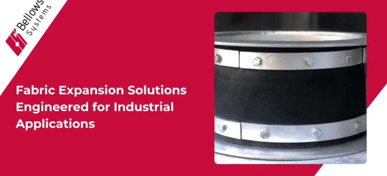
Fabric expansion joints are essential components designed to manage movement and vibration in various industrial systems. At Bellows Systems, Inc., a leading custom-engineered bellows and expansion joints manufacturer in Houston, Texas, US, we specialize in fabric expansion joints tailored to specific industrial requirements.

Understanding Fabric Expansion Joints

Importance of Fabric Expansion Joints

Fabric expansion joints absorb thermal movements, isolate vibrations, and accommodate misalignment in ductwork and industrial systems, enhancing operational efficiency and system longevity.

Applications Across Industries

  • Power Generation: Handling flue gases and air ducts
  • Cement Industry: Managing kiln exhausts and dust collection systems
  • Pulp and Paper: Accommodating dryer exhaust movements
  • Chemical Plants: Dealing with corrosive fumes and high-temperature air

Why Fabric Expansion Joints?

Advantages Over Traditional Joints

Fabric expansion joints from Bellows Systems offer:

  • Excellent flexibility and vibration absorption
  • Lightweight and easy installation
  • High resistance to corrosion and chemicals
  • Cost-effective maintenance and replacement

Material Selection for Fabric Expansion Joints

Selecting appropriate materials ensures reliable performance:

  • PTFE (Teflon): Outstanding chemical resistance and flexibility, ideal for corrosive environments.
  • Fiberglass: Excellent heat resistance and durability, suitable for high-temperature air and flue gas ducts.
  • Elastomers (EPDM, Silicone): Provide good flexibility, chemical resistance, and weatherability, perfect for vibration isolation.

For more details, explore our fabric expansion joints product page.

Bellows Systems' Custom Fabric Expansion Joint Solutions

Tailored Engineering

Bellows Systems, Inc. designs each fabric expansion joint solution based on your unique operational conditions, ensuring optimal performance and reliability.

Industry-specific Solutions

  • High-Temperature Applications: Custom-engineered fiberglass solutions effectively manage extreme thermal conditions
  • Corrosive Environments: PTFE-lined joints provide superior resistance against aggressive chemicals.
  • Flexible Installations: Elastomer-based joints efficiently isolate vibrations, improving overall system stability.

Comprehensive Quality Testing

All fabric expansion joints meet strict quality and performance standards, ensuring safe and effective operation in demanding conditions. Review our detailed engineering standards to learn more.

Benefits of Custom Fabric Expansion Joints

  • Reduced vibration and noise
  • Enhanced operational efficiency
  • Lower maintenance costs
  • Increased equipment lifespan

Frequently Asked Questions

When should I choose fabric over metal expansion joints?

Fabric joints are preferable when lightweight, flexible vibration absorption and corrosion resistance are priorities, especially in low-pressure air or gas systems.

What maintenance do fabric expansion joints require?

Minimal regular inspections for wear and tear are recommended. Fabric expansion joints from Bellows Systems generally require very low maintenance.

Are fabric expansion joints durable enough for harsh industrial environments?

Yes. Our fabric joints use high-grade materials engineered specifically to withstand harsh conditions, including extreme temperatures and corrosive environments.

For additional details about our industry-specific solutions, visit our applications page.

Ready for a Customized Fabric Expansion Joint Solution?

Consult with Our Experts Today!

Choose Bellows Systems, Inc.—your trusted custom-engineered bellows manufacturer in Houston, Texas, US—and get precisely engineered fabric expansion joint solutions tailored for your specific industry and operational needs.

Read More
Precision in Every Joint: Custom Expansion Solutions Built for Oil & Gas Pipeline Reliability!

Managing Thermal Expansion in Oil & Gas Pipelines: Custom Expansion Joint Solutions

Thermal expansion in pipelines is a critical issue faced by the Oil & Gas industry. Pipelines frequently undergo temperature fluctuations, causing significant stress and potential operational hazards. At Bellows Systems, Inc., as a leading custom-engineered bellows manufacturer in Houston, Texas, US, we specialize in addressing precisely these challenges.

Understanding the Challenge

Why is Thermal Expansion a Critical Issue?

In Oil & Gas pipelines, temperature variations cause pipelines to expand and contract, creating stress that leads to potential leaks, equipment failure, and costly downtime. Unmanaged thermal expansion can compromise safety, environmental compliance, and operational efficiency.

Common Problems Caused by Unmanaged Thermal Expansion

  • Pipeline cracking and leaks
  • Equipment and anchor damage
  • Environmental and safety hazards

Real-world Consequences

Imagine an offshore pipeline failure due to unmanaged thermal expansion: this could result in massive revenue loss, environmental damage, safety risks, and extensive repair costs.

Why Traditional Solutions Fail

Common Mistakes in Managing Pipeline Expansion

  • Overuse of rigid supports, preventing needed flexibility
  • Choosing incorrect or substandard materials
  • Underestimating the extent of thermal movements

Why Generic Expansion Joints May Not Be Enough

Generic expansion joints might fail due to incompatibility with extreme pressures, temperatures, and corrosive conditions typical of Oil & Gas applications.

  • Overuse of rigid supports, preventing needed flexibility
  • Choosing incorrect or substandard materials
  • Underestimating the extent of thermal movements

The Custom Engineered Solution – Metal Expansion Joints

Introduction to Metal Expansion Joints

Metal expansion joints are specially designed components that absorb thermal movement and reduce pipeline stress. They ensure structural integrity and continuous operational reliability.

Types of Expansion Joints Ideal for Oil & Gas

Material Selection for Oil & Gas Conditions

Selecting the right material is crucial for long-term pipeline reliability:

  • Austenitic Stainless Steels (316/316L, 321): Provides corrosion resistance, strength, and durability.
  • Nickel Alloys (Inconel, Monel): Ideal for extreme temperature resistance, corrosion protection, and structural stability under severe conditions.

Bellows Systems' Custom Engineering Advantage

Tailored Solutions for Oil & Gas Pipelines

At Bellows Systems, Inc., each expansion joint solution is engineered specifically for your pipeline’s operating environment, ensuring precise performance and long-term reliability.

Advanced Engineering and Material Selection

Our engineering team conducts thorough analysis of pipeline operating conditions, choosing the optimal material and joint design to withstand extreme pressures and temperatures.

Rigorous Testing and Compliance Standards

All Bellows Systems expansion joints comply with industry standards (ASME, AWS) and undergo rigorous testing, ensuring exceptional quality and performance.

Case Study Spotlight

We recently custom-engineered high-pressure balanced expansion joints for an offshore Oil & Gas client. The solution effectively managed extreme thermal fluctuations, significantly reducing downtime and maintenance costs.

Benefits of Custom Expansion Joints for Oil & Gas Pipelines

  • Reduced risk of pipeline stress and failures
  • Improved safety and regulatory compliance
  • Lower maintenance and downtime costs
  • Enhanced operational efficiency and system longevity

Frequently Asked Questions

Consider factors like pressure, temperature, fluid type, and movement magnitude. Our experts guide you through a detailed analysis to select the right joint.

Absolutely. Our customized joints are specifically engineered to handle high pressures, temperatures, and corrosive environments typical of the Oil & Gas industry.

Regular visual inspections and periodic pressure tests are recommended. Properly engineered joints from Bellows Systems generally require minimal maintenance.

Why Choose Bellows Systems, Inc.

Decades of Industry Expertise

With over 45 years of specialization, Bellows Systems, Inc. is trusted across the Oil & Gas industry.

Houston-based Custom Manufacturing

Our Houston, Texas facility ensures rapid response, personalized service, and localized expertise.

Industry-proven Solutions

Our solutions consistently outperform standard products in rigorous Oil & Gas applications.

Ready to Solve Your Thermal Expansion Challenges?

Talk to Our Bellows Engineering Specialists Today!

Don’t wait for a pipeline issue to become critical. Contact Bellows Systems, Inc.—your trusted custom-engineered bellows manufacturer in Houston, Texas, US—and experience tailored solutions designed for your unique Oil & Gas pipeline needs.

Read More
Customized Fabric Expansion Joints Engineered for Ultimate Industrial Performance!

Fabric Expansion Joints: Custom Solutions for Industrial Applications

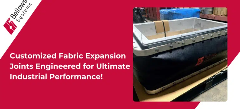
Fabric expansion joints are essential components designed to manage movement and vibration in various industrial systems. At Bellows Systems, Inc., a leading custom-engineered bellows and expansion joints manufacturer in Houston, Texas, US, we specialize in fabric expansion joints tailored to specific industrial requirements.

Understanding Fabric Expansion Joints

Importance of Fabric Expansion Joints

Fabric expansion joints absorb thermal movements, isolate vibrations, and accommodate misalignment in ductwork and industrial systems, enhancing operational efficiency and system longevity.

Applications Across Industries

  • Power Generation: Handling flue gases and air ducts
  • Cement Industry: Managing kiln exhausts and dust collection systems
  • Pulp and Paper: Accommodating dryer exhaust movements
  • Chemical Plants: Dealing with corrosive fumes and high-temperature air

Why Fabric Expansion Joints?

Advantages Over Traditional Joints

Fabric expansion joints from Bellows Systems offer:

  • Excellent flexibility and vibration absorption
  • Lightweight and easy installation
  • High resistance to corrosion and chemicals
  • Cost-effective maintenance and replacement

Material Selection for Fabric Expansion Joints

Selecting appropriate materials ensures reliable performance:

  • PTFE (Teflon): Outstanding chemical resistance and flexibility, ideal for corrosive environments.
  • Fiberglass: Excellent heat resistance and durability, suitable for high-temperature air and flue gas ducts.
  • Elastomers (EPDM, Silicone): Provide good flexibility, chemical resistance, and weatherability, perfect for vibration isolation.

For more details, explore our fabric expansion joints product page.

Bellows Systems' Custom Fabric Expansion Joint Solutions

Tailored Engineering

Bellows Systems, Inc. designs each fabric expansion joint solution based on your unique operational conditions, ensuring optimal performance and reliability.

Industry-specific Solutions

  • High-Temperature Applications: Custom-engineered fiberglass solutions effectively manage extreme thermal conditions.
  • Corrosive Environments: PTFE-lined joints provide superior resistance against aggressive chemicals.
  • Flexible Installations: Elastomer-based joints efficiently isolate vibrations, improving overall system stability.
    Comprehensive Quality Testing

All fabric expansion joints meet strict quality and performance standards, ensuring safe and effective operation in demanding conditions. Review our detailed engineering standards to learn more.

Benefits of Custom Fabric Expansion Joints

  • Reduced vibration and noise
  • Enhanced operational efficiency
  • Lower maintenance costs
  • Increased equipment lifespan

Frequently Asked Questions

Fabric joints are preferable when lightweight, flexible vibration absorption and corrosion resistance are priorities, especially in low-pressure air or gas systems.

Fabric joints are preferable when lightweight, flexible vibration absorption and corrosion resistance are priorities, especially in low-pressure air or gas systems.

Minimal regular inspections for wear and tear are recommended. Fabric expansion joints from Bellows Systems generally require very low maintenance.

Yes. Our fabric joints use high-grade materials engineered specifically to withstand harsh conditions, including extreme temperatures and corrosive environments.

For additional details about our industry-specific solutions, visit our applications page.

Ready for a Customized Fabric Expansion Joint Solution?

Consult with Our Experts Today!

Choose Bellows Systems, Inc.—your trusted custom-engineered bellows manufacturer in Houston, Texas, US—and get precisely engineered fabric expansion joint solutions tailored for your specific industry and operational needs.

Read More
DMCA.com Protection Status